In this piece, let’s discuss “how does a resistor work?” and also explain what happens to voltage and currents when resistors are connected in:
- Series
- Parallel
At the end, you will know how to read resistor color band codes and other essential information about resistors.
Let’s dive in now.
What Do Resistors Do?
⦁ Resistors functions to protect the electrical circuit’s components against voltage spikes
⦁ Limit the flow of electric currents in an electrical circuit
⦁ Restrict and redirect current & voltage to fit a particular engineering project
⦁ Ensure the appropriate amount of voltage is distributed across components by creating a voltage drop
⦁ Current flow dividing
⦁ Impedance matching to maximize power transmission at high frequencies
⦁ Reduce noise issue on chips with high-speed busses
Common Resistors
⦁ Fixed Value Resistors – Most predominant resistors ranging from 100 to 100K ohms
⦁ Variable Resistors – Adjustable resistance is also known as a rheostat. Photoresistors for example can change based on light
⦁ Resistor Networks – Array of resistors primarily act as voltage dividers
Common Resistor Analogy
A water-pipe analogy is commonly used when describing the effect of resistance on voltage in an electrical circuit. In this analogy:
⦁ The charge is represented by the amount of water flowing through the pipe.
⦁ The voltage is represented by the pressure of the water flowing through the pipe.
⦁ The water flow itself represents the current.
Here is an easier way to illustrate this with water:
- The Resistor = Tightening of the pipe to restrict water volume flow & speed
- The Voltage = The Pressure of the water flowing through the pipe
- The Current = The amount of water volume passing through a point
The water represents the charge. In another word, more water means more pressure at the end of the hose.
We can relate this concept to electrical flow
⦁ Resistors are things inside the wire to slow down the current
⦁ Current also represents the size of the wire allowing more or less electrical flow (Thick wire carries more load, and it’s more expensive)
⦁ Voltage is the pressure of the electrical flow
Resistors in Series; What Happens to Currents and Voltage?
When resistors are connected in series, the current through each of the resistors stays the same.
The voltage in a series-connected electrical circuit equals the sum of all the voltages across each of the resistors.
Let’s take a look at this circuit as an example:
In the above circuit, the following applies:
I1 = I2 = I3
VT = V1 + V2 + V3
RT = R1 + R2 + R3
In this particular series circuit, it’s pretty straightforward to just add up the resistance value, current value, and voltage value altogether.
Resistors in Parallel; What Happens to the Currents and Voltage?
When resistors are connected in a parallel circuit, the supply current is directly proportional to the sum of the total currents through each of the resistors.
In parallel circuits, there are branches. So, the branches of this circuit sum up the supply current.
On the other hand, resistors connected in parallel have similar potential differences or voltage across them. Similarly, any of the participating components in that parallel circuit has the same potential difference across them.
How Do You Calculate the TOTAL RESISTANCE in Parallel Circuit?
The total resistance of two resistors connected in parallel can be calculated with the formula below;
1 = 1 + 1
R R1 R2
If, for instance, you have three resistance connected in parallel, you’ll have to add the third resistor to the equation above. It then becomes;
1 = 1 + 1 +1
R R1 R2 R3
All these indicate that the components of a parallel electrical circuit tend to decrease the total resistance in that circuit.
What Does Resistor Color Bands Mean?
Resistor Color bands indicate the following:
- Tolerance
- Temperature coefficient
- Resistance value
The body of a resistor can have anywhere from between 3-6 colored bands.
The most common variation you’ll find all around is the resistors with four colored bands.
How to Read Resistor Color Codes
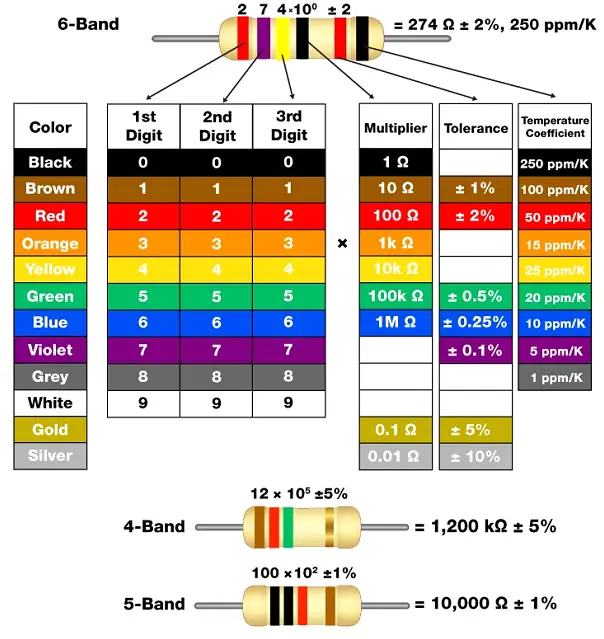
Three or Four Band Resistors
The first two bands usually denote the first two digits of the resistance value measured in ohms.
The third band represents the multiplier value – The primary role of a multiplier is to shift from megaohms to milliohms and anywhere in between.
The fourth color indicates tolerance – The function of tolerance represents the error percentage in the resistor’s resistance.
Here is how to make sense while looking at the numbers:
If the fourth band is absent and you are in search of a three-band resistor, the tolerance is default at a value of ±20%.
If you want to determine whether a band is first or last, you’ll have to spot the tolerance band as it is usually distinctly separated from the value bands.
More importantly, the tolerance bands is either in two colors; gold or silver.
Five or Six Band Resistors
A five-brand resistor with an extra ring represents the TEMPERATURE COEFFICIENT (ppm/K) or failure rate.
The sixth band has the most common color brown color (100 ppm/K), which means for every 10 degree Celsius change, the resistance value also increases by 0.1%.
Here is an example:
Follow the guide above:
Let’s take a look at this 4 band 4.7Ω resistor
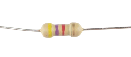
⦁ Yellow corresponds to 1st digit – 4
⦁ Violet corresponds to 2nd digit – 7 (combine 1st & 2nd together to get 47)
⦁ Red corresponds to a multiplier value of 100
⦁ Gold corresponds as tolerance 5%
So this resistor can be read as:
47 * 100 = 4700 ohms (+/-) 5% tolerance
Tips for Reading Resistance Color Band Codes
Pro Tip: Use a mnemonic to help you remember.
Better Be Ready Or Your Great Big Venture Goes West
Black (0), Brown (1), Red (2), Orange (3), Yellow (4), Green (5), Blue (6), Violet (purple, 7), Gray (8), and White (9)
⦁ 1st – 3rd digits & multiplier band represent resistance value
⦁ The first band always serves as the direction that is closest to a lead
⦁ The tolerance band which can either be in gold or silver color is the last band
⦁ Resistor never start with the metallic band on the left
Checking the manufacturer’s documentation is always a good practice as it will serve as a good guide
Whenever you are in doubt, just use an ohmmeter to check the resistance. It’s easy and saves time.
Wrap Up
Here you have learned:
What resistor does in electrical circuits
Common resistor analogy
The effect of resistors on voltage and currents when connected in series and parallel
Tips on how to read resistor color bands
Now that you know the basics of resistors, what they do in electrical circuits, and their color bands, get out there and implement this in your DIY projects.